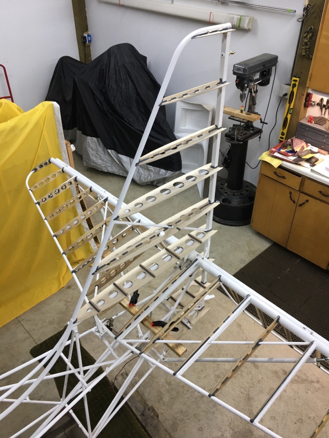
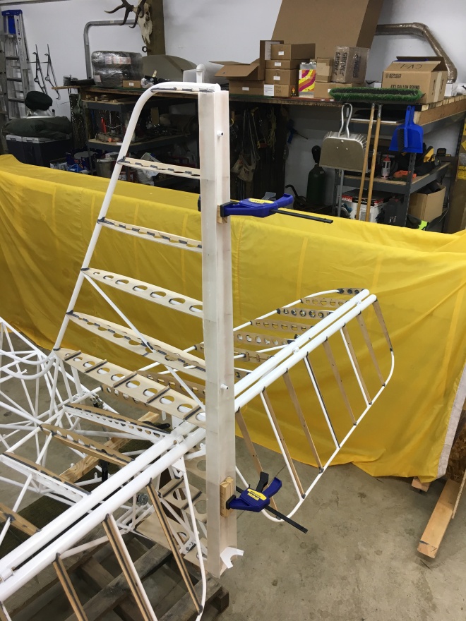
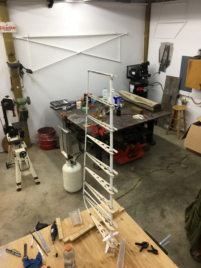
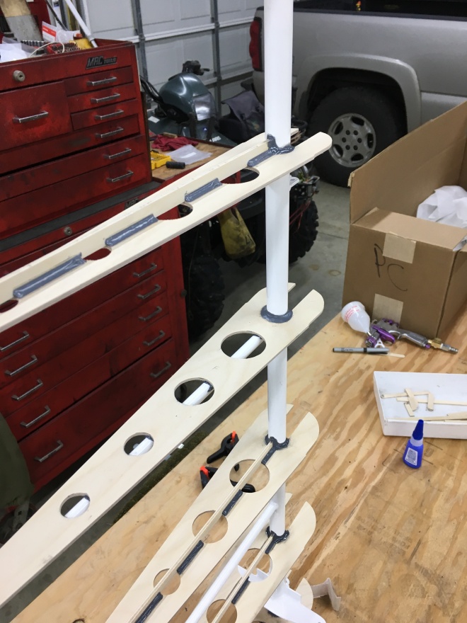
Next part of the build is to level the fuselage front to rear and left to right. I put it on jack stands at the recommended point but in the future it will be blocked at the front. It will be much more stable and i need it higher also.I had to weight the aft end to keep the fuselage from tipping forward, used a bucket of lead.This pic shows the foot print in my work space. Just wanted to be sure there was room to work all the way around.Here the left wing is in place.And a pic of both wings on.This is a pic of the right rear spar with the bolt holding it to the carry-through tube.This is the right front spar. There is no hole drilled yet. First both wings need to be trimmed. First is to set the wing sweep which is determined by the weight of the engine. A Rotax 912iS is my choice so wing sweep will be 0 degrees. After the wing sweep is to set the dihedral which is set at 1 degree, and last is washout. These measurements were made with the utmost care and checked and rechecked………Its crucial that this is done correctly be cause the next step is to drill the hole in the front spar.
I haven’t posted for a while due to the holidays but enjoyed time with family. I have been busy with the bubble doors and have gone as far as possible until the wing roots are in place. I probably won’t finish the doors completely until the end of the build. This pic shows the acrylic being fitted.Here is a closeup. I opted to use riv-nuts, aka blind hole nuts, to secure the acrylic instead of machine screws that go all the way through the frame.I also opted to use the dual latch door latches. This slot and the two holes are where the door handle is attached.Here is a closeup of the latch.Both sides are to this point and will be set aside for now. Next up is to mount the wings. I have some studying to do!
Finished the last details on the vertical and rudder so I mounted the rudder to check the height and overall look. I am pleased with the outcome.Left rudder.A view from the top.
Same profile as a P-51Here is the left stringer bonded and riveted.Left door frame and triangle window bonded and clamped. Did I say clamped?Same goes for the right side. Cutting and fitting the angles took some thought but no wrong cuts were made. There is no extra material for mistakes!And more clamps.Take a close look and see the door blocked in the opening. The next step is to fit the bubble doors. They are acrylic and crack easily.I cut off the excess material using a dremil with a cutoff wheel.Here it is placed in the doorway. The protective plastic covering will stay on until the project is complete. Next will be fastening the acrylic to the frame at 14 points, fitting the dual pin latch and the hinges. The doors swing upward aka gull wing doors.
It took quite a bit of sanding/shaping On the top of the vertical and rudder but I am pleased with the outcome. I will spray epoxy primer on the top of the vertical, rudder as well as the ends of the horizontal and elevator.Here is the rudder top, nice and streamlined.Next up are the door frames, triangle windows and stringers. Here are the lower and rear frames.This is the triangle window clamped and clecoed in place.Here is a pic of the stringer clecoed in place. I prepped all of this at one time because they all tie together at one point. Next I will remove all of it, deburr all of the drilled holes, prep all of the surfaces, then bond, clamp and rivet it all together. After all that, the other side needs to be done. Fun stuff!
I have worked on several areas the last few days. First was a coat of hysol on the rudder top and vertical top. This was allowed to cure for a few days then sanded down. The rudder was close to what I’m trying shape but needed another coat to get there.Same with the vertical but it’s probably going to take several applications of hysol to get it right.In the meantime I moved on to fit the seat pan. This is a pic of a nut plate. It’s on backwards so that I can back drill the rivet holes. There are six mounting tabs, two on the top and four on the bottom.This shows the nut plates riveted in place.Just one pic of the seat pan. There was a lot of cutting,fitting and sanding involved to fit this in place. The slots are for the four point harnesses to fit through.Just got started fitting the aluminum stringers. There are three, one on each side and the bottom.
While the fiberglass fairing hysole is curing I focused on attaching the angle on the lower full length rib. There are three angles on each side one on the bulkhead, rib and one small rib below the long one. These angles will be attaching points for the horizontal close out panels. More on that later in the build.This pic shows both angles riveted/bonded in place.This is the rear lower angle riveted/bondedHere is a pic of rough shaped pieces of balsa wood bonded to the top of the vertical and rudder. While this is curing I am hoping to get the rudder cables installed.Here is my first time using a Swaging Tool, turned out great.Here it is finished off with shrink tubing.Easy to use, handy tool in my tool box.I have the optional adjustable rudder pedals, so here is a pic of the cables attached to the adjuster levers.The cables a routed through these pulleys. The pink paper clips have been replaced with the appropriate cotterpinsThis is where the co-pilot cables are married to the pilot cables midway on the fuselage. The last thing to do for the rudder cables is to attach them to the rudder. This is done after the covering/painting is completed.This is the top of the rudder with the balsa roughed out. It will require more hysol and sanding to finish it off.This is the top of the vertical stabilizer with the balsa roughed out. Same procedure as the rudder. I will apply another coat of hysol so while this is curing on to fitting the seat pan!
It has been about a week since I have posted, but progress has been good. All of the ribs on the vertical stabilizer and rudder are bonded in place and have two coats of epoxy varnish. The varnish has dried so time to hysol the fiberglass fairings in place. This pic shows the rudder leading edge fairing on the left and the vertical fairing on the right prepped and ready to be bonded.This pic shows the fiberglass fairings being test fitted.Another view.Close up pic. The horizontal stabilizer and rudder are going to be removed now to make it easier to bond the fairings in place.Here is the vertical piece bonded and clamped.A little creative clamping. Whatever it takes to hold it in place!Here is the rudder with the fairing bonded in place. Some good strong tape used to keep it in place.This is the bulkhead being test fitted. The thin strip of angle is where the front of the horizontal access panel will attach. While the fairing hysol is curing I will finish the bulkhead and start working on the rudder cables.
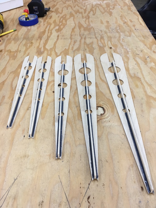
I am finished with the controls in the cockpit so now its time to work on the vertical stabilizer and rudder. These are fully faired with wood ribs similar to the ones used for the horizontal stabilizer and elevator. This pic shows all of the ribs (9) hysoled in place. Still needs at least two coats of epoxy varnish.This pic shows the aft vertical fair clamped in place. There is still some fitting and sanding to do.On to the rudder. Here it is screwed to the bench with the four ribs that are hysoled to the horizontal frame parts. These take quite a bit of bonding so I did them one day and let the hysoled cure for twelve hours or so.Here are the last five ribs prepped, with longitudinal stiffeners hysoled in place ready to install. I prepped these about twelve hours ahead of time also.This pic shows all of the ribs in place. The hysol needles to cure and then two coats of epoxy varnish. The rudder also has a fiberglass fair on the leading edge that contours with the vertical.Here is a close up of a few of the ribs attached.
Made progress on the console, detent for flaps and rudder pedals hysoled and riveted in place. Still need to add the parking brake valve, fuel shut off valve and possibly a throttle to the center console.Fitted the right side panel. Still need to drill mounting holes on this side then work on the left side.Also completed the master cylinder(s) so all of the pedal work is complete except for rudder cables.
A little side project in the shop was to upgrade the lighting. Originally there were ten eight foot dual high output fluorescent lights. They worked well but buzzed pretty loud on cold days and sucked power. Converted the same fixtures to LED, bypassing the ballast. Result no buzz, 30% more light and 65% less power!Next problem to solve was to figure out a way to drill a 1/16” hole in a 1/4 x 1” piece of round stock. Pictured is a halfback inch plate with a 1/16” hole drilled in it. All I was trying to do was drill straight on one axis. It took me three try’s with a cordless drill to get it right.Then I scribbled a line down the side of the plate and drilled a hole intersecting the 1/16 “ hole dead center. That hole is the same diameter as the 1/4 stock.Then I centered the 1/4 “ stock and drilled the 1/16” hole.Perfecto! Two pieces with perfectly centered holes.These parts are for the adjustable pedal levers. The pins fit into detents and hold the rudder pedals at the desired position.